Links
Tags
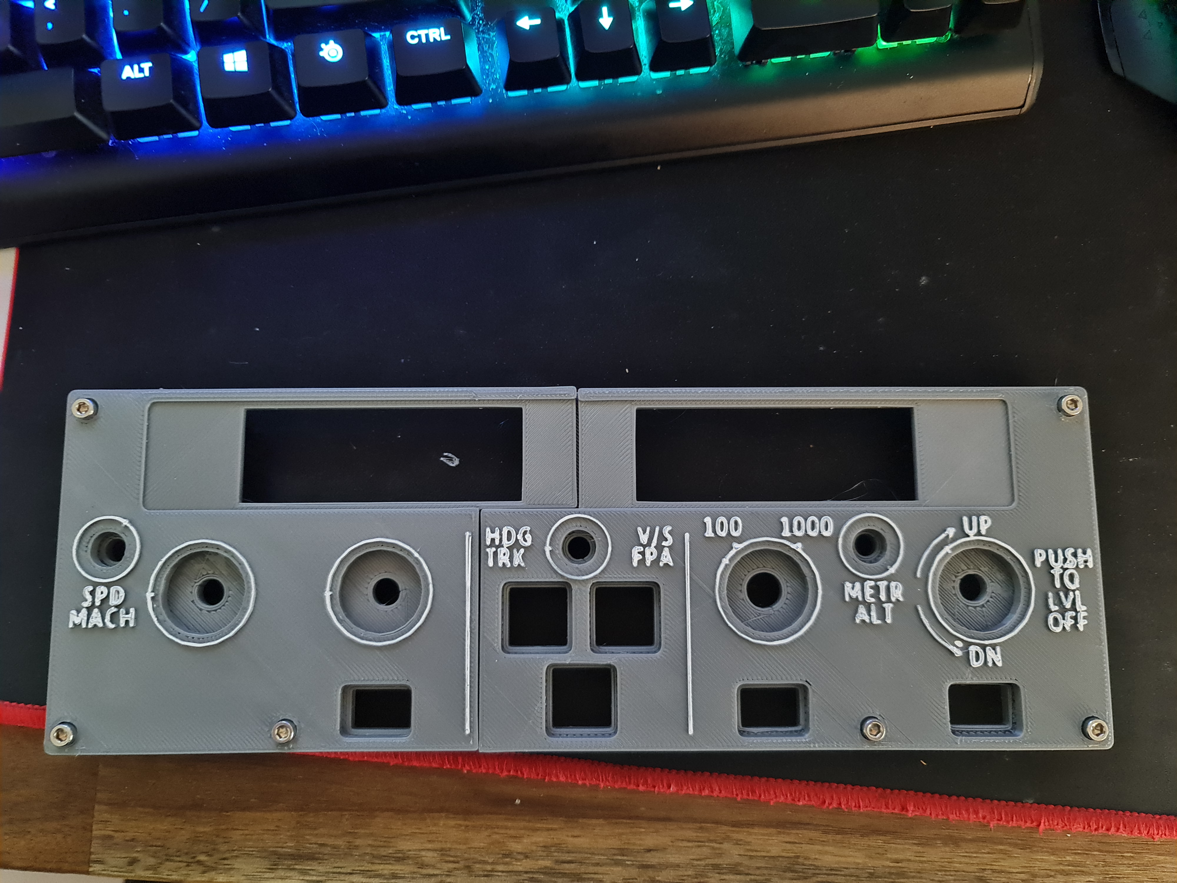
Knobs, Wiring and Buttons - Progressing on the A320 FCU
I haven't had a lot of time the last few weeks to work on the FCU much further, however there are a couple of updates worth sharing.
Minor redesign to the back plate
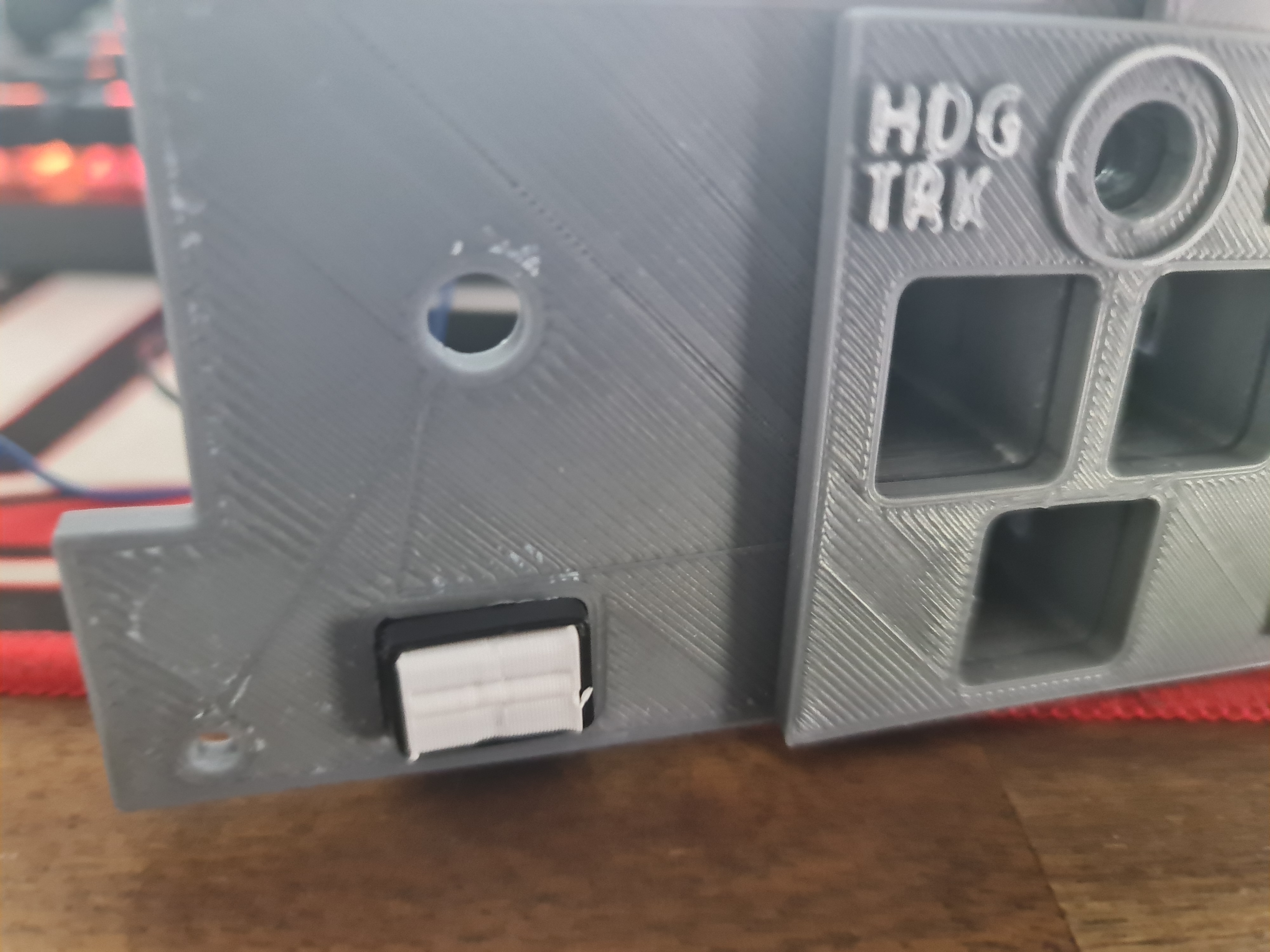
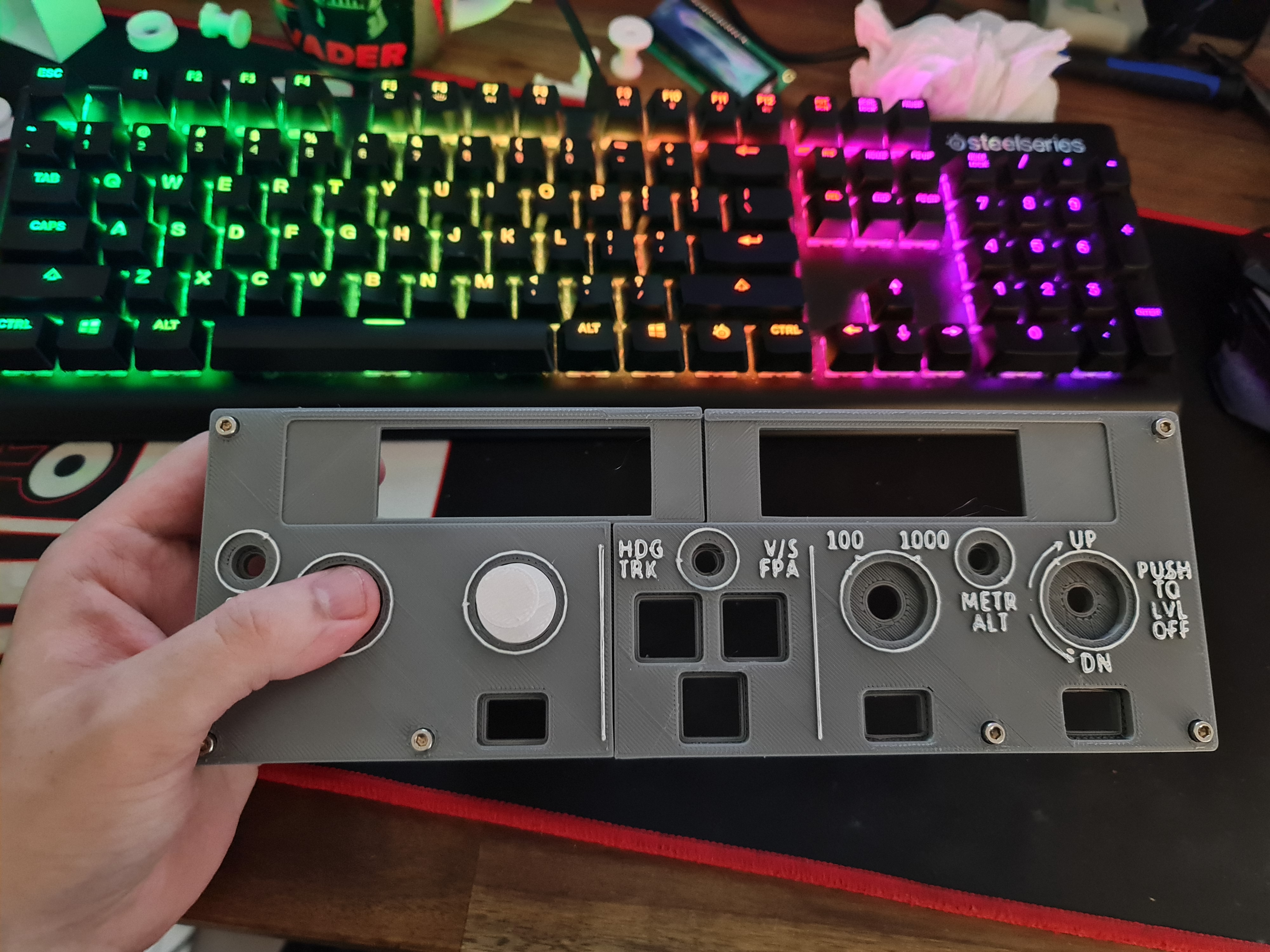
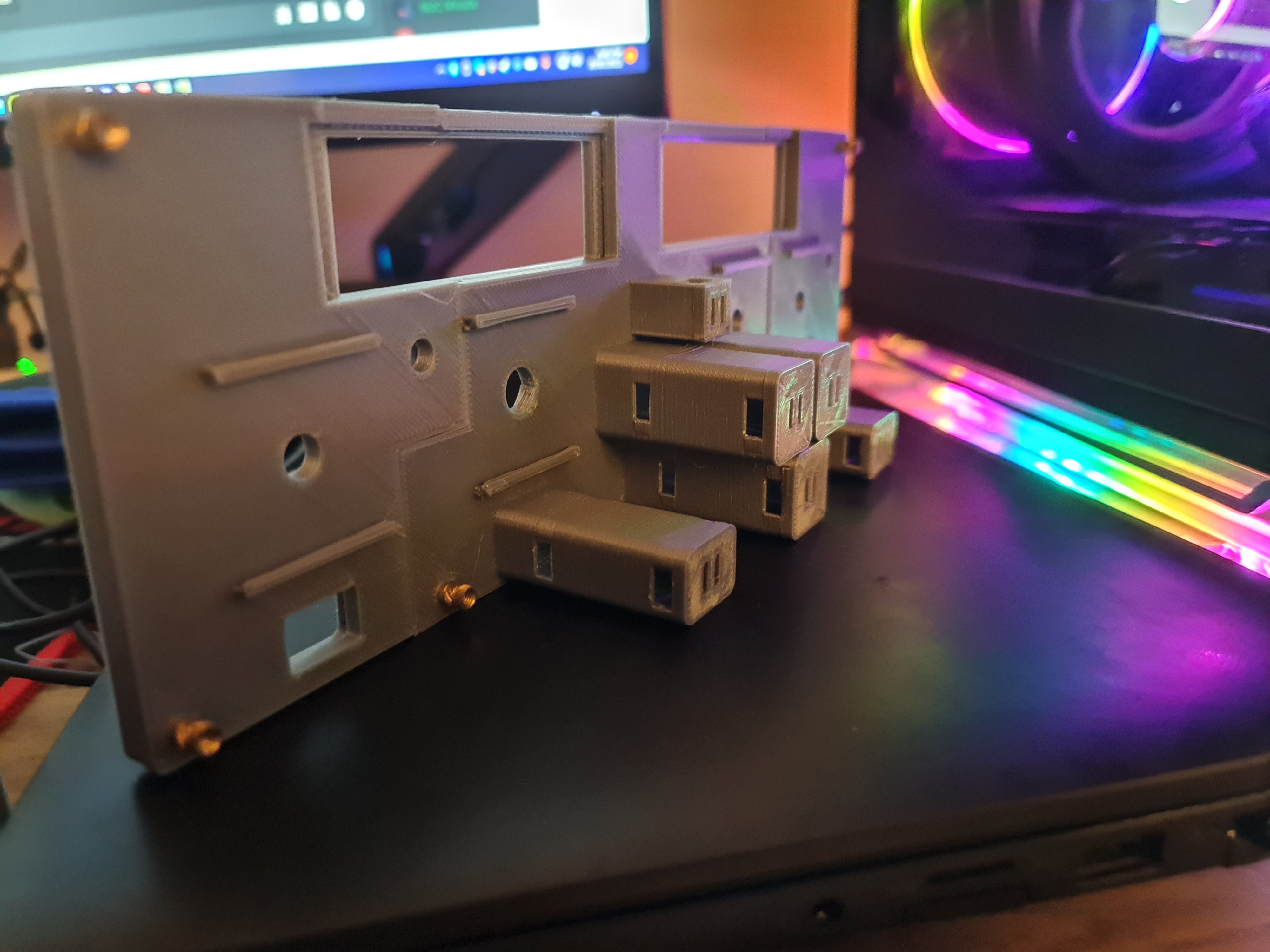
I had this grand idea to make insertable Korry's into place and have them as removable independent units. Unfortunately, those LED lights wouldn't fit inside the chamber I had printed and the outcome wasn't great. To get around the need to glue and design all of those components, I had completed another design - this time where the chamber was integrated to the backplate. As I wasn't too sure about the tolerances here, I had printed a few different sizes to work with the Korry inserts but I really only had one shot at getting the backplate done.
With this out of the way, the next step was to insert buttons and led lights into each of these new chambers. Again, this took several goes that I had pre-empted and thus the creation of different sizes - but thankfully things like leaving a large gap to slip the buttons in really helped out here. It was fiddly though, and you really get to know just how tight (i.e. < 0.1mm inaccuracies) things may fit or require a bit of filing and cutting to get things in snug.
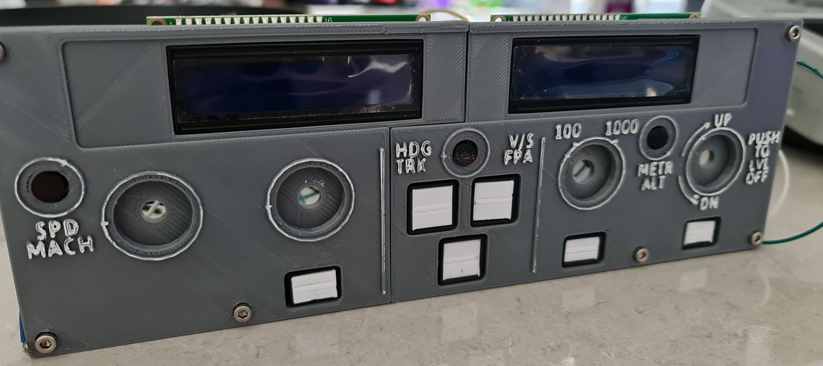
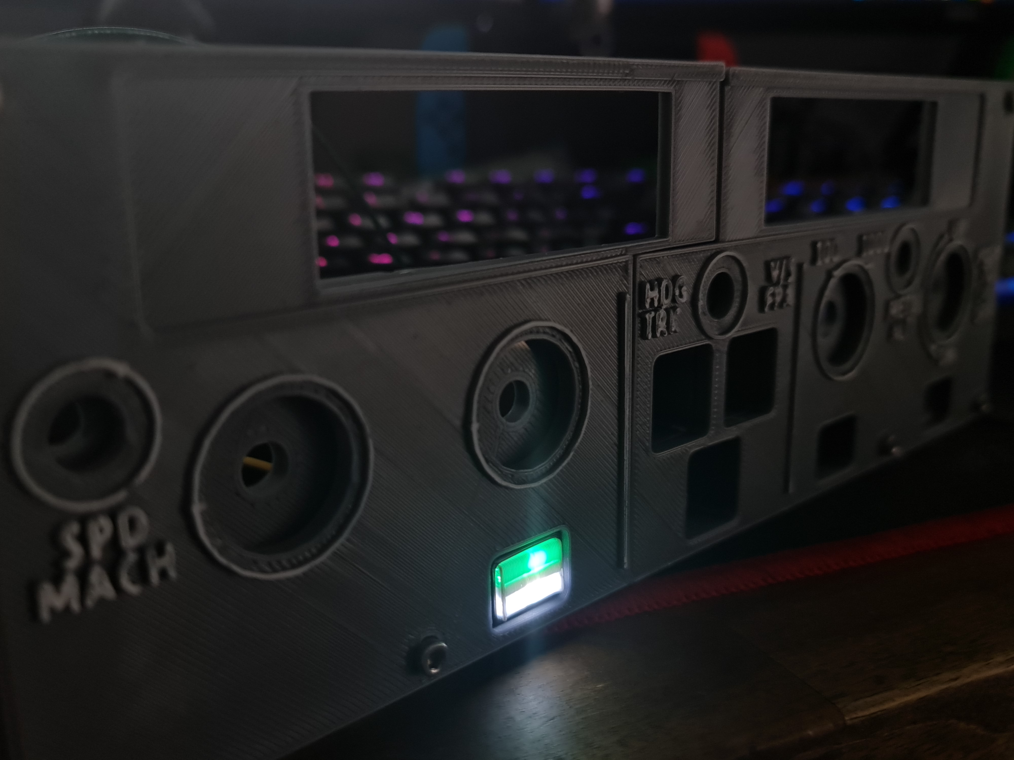
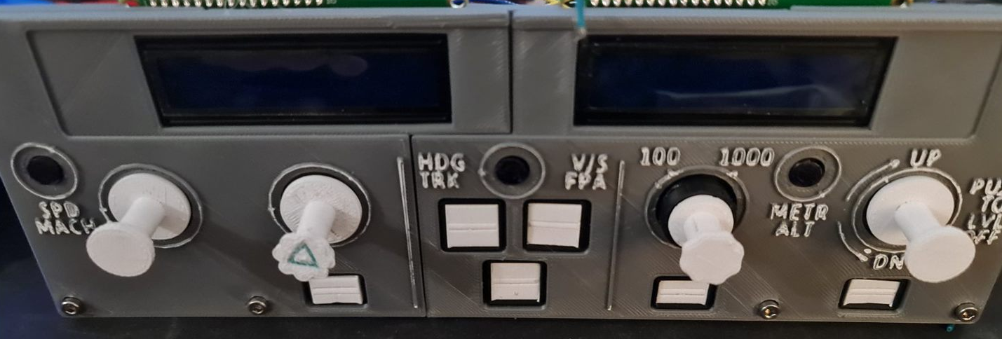
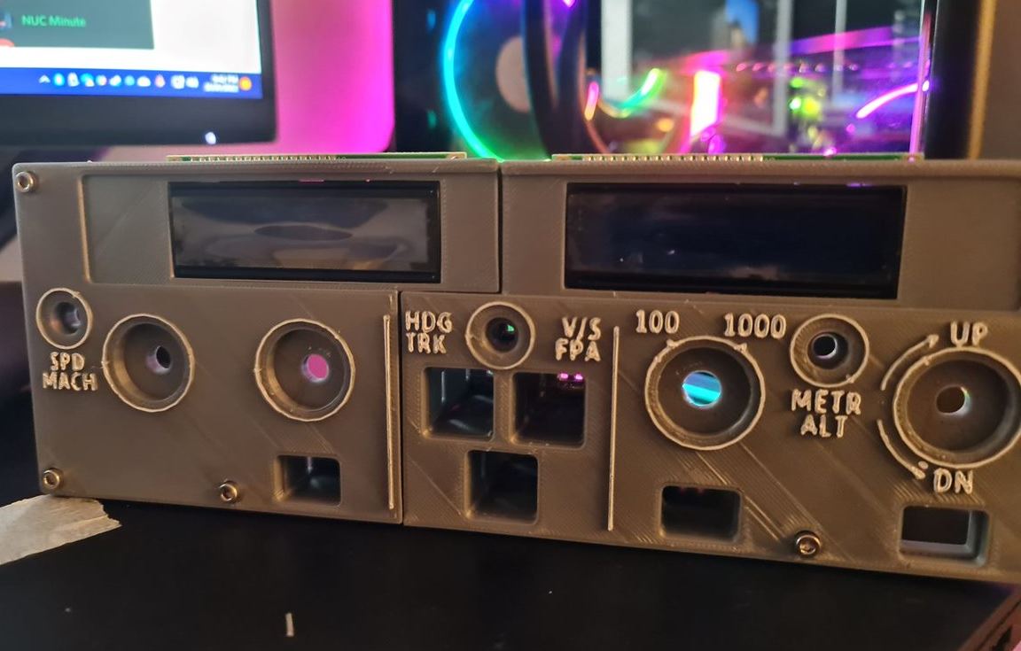
With the screens in place, it's starting to come along.
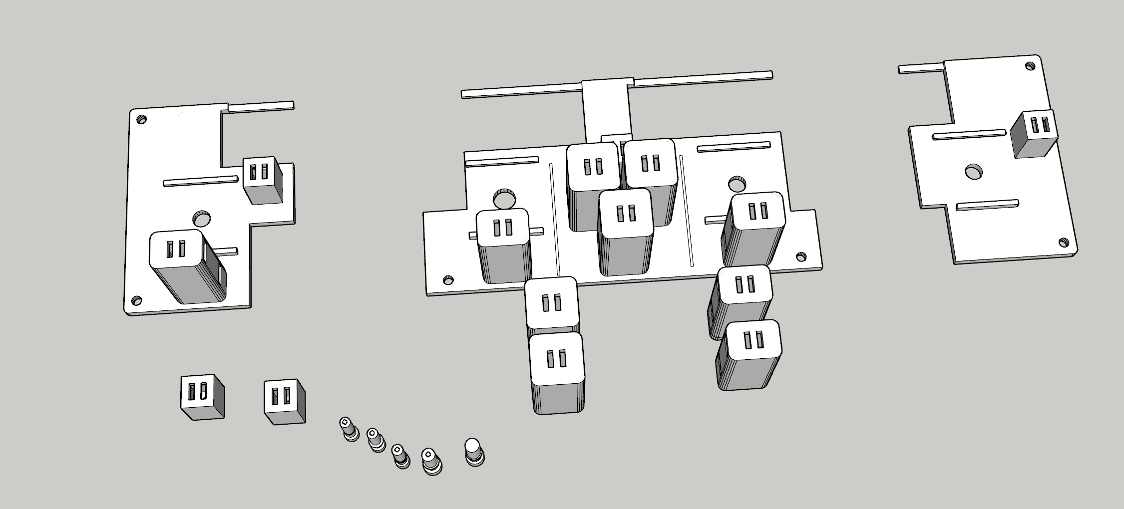
Installing the Rotary Encoders
I've spent a bit of time going back and forth on getting a good, repeatable push-pull rotary encoder working and in the middle of doing this had learned a few more quirks about the printer - especially printing such small volume items. For the Rotary Encoders in particular, when I began I was printing shells, stalks and knobs altogether with the same material. As I started printing smaller volumes, I started getting stringy mess and prints that wouldn't be loose enough around the rotary encoder itself.
Having not had to level this printer for a few months, I figured at the very least I'd clean up the bed, re-level it manually and give the internals a good clean too (ensure the filament isn't slipping in the extruder from a build-up of gunk). I'd 3D Print a calibration cube and everything was within known tolerances (< 0.1mm on the Z axis but otherwise everything else recorded a perfect 2mm). I had printed a few other things at the same time and they also come out well without stringing. It finally dawned on me that perhaps the part was 'too hot' and wasn't given enough time to 'cool down' before applying the next layer. So to remedy the next print, instead of printing one stalk - I printed all the working parts and things kind of went back to normal.
The reality is that when you start playing with your printer - you start having to 'learn' all the quirks again. Having a more level bed and now knowing about volume of prints to help dissipate heat means you're back to calibrating your software settings to compensate too. So it's fair to say that it took quite a few goes before usable prints were coming out.
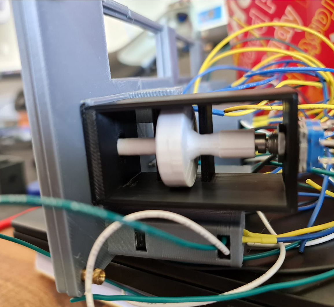
With the first prototype in place things are looking on the up. This particular switch has the right clearance off the button at the back and works perfectly. I perhaps had unrealistic expectations that the same will occur for the other ones - but unfortunately it didn't quite work that way. For the second rotary encoder, the disc didn't quite go all the way down on the rotary encoder so the disc itself in the 'release' mode was touching right up against the pull mechanism - not a great outcome. It's fair to say that in hindsight, I would probably use a longer stalk button to remove that margin of error and perhaps had a bit more of a gap and maybe a spring to help. In any case, something to improve on.
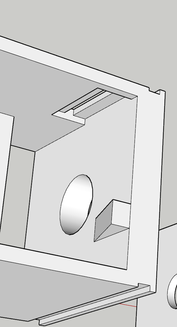
Things get a bit more challenging for the altitude selector. There's an outer ring that selects either increments of 100 or 1,000 - this would need to sit around the stalk and be some kind of a compression fit to hold the selection. I don't expect this mechanism to last long - and perhaps a second encoder or toggle switch might have helped (there are plenty of options on Thingiverse). Behind the scenes would be a microswitch that by using very little friction at all, can sit on the microswitch when activated.
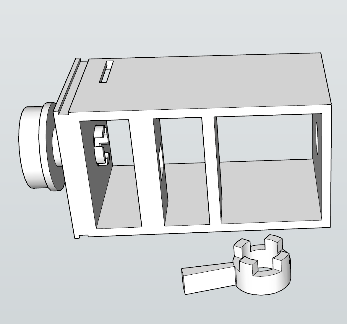
With the selector and activator connected together, and the microswitch installed - we should be able to select 100 or 1,000 with some creative license by rotating the ring. The final piece of the puzzle was working out how far the grip should protrude. Apart from having to print this a few times, this was perhaps the easiest part to assemble and now the knob and selector fit reasonably well.
What's next?
I'm at the final stages now of the assembly itself leaving behind some fiddly and trivial components.
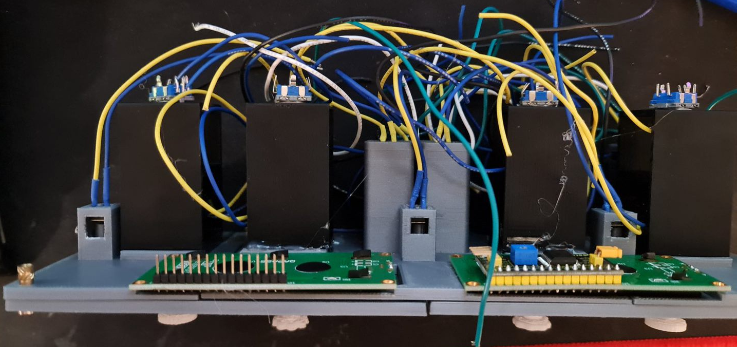
- An Arduino Mega 2560 needs to be wired up. I've got some proto boards ready to solder all the wires to.
- A shell for the components to sit in. This is currently printing whilst typing.
- Printing some Korry labels - this will likely be a transparency on a white sheet of paper.
- Get this all running and working in Flight Simulator, via SimConnect.
- Final decorations - black shroud for the LCD screens for example.
It's fair to say that should this be a repeatable design, I think I would embrace sacrificing imitation for simplicity. For example, the Korry 'pull' action might very well be replaced with additional push buttons on the face. That would then leave the rotary encoders available for a very simple installation. The same applies for the 100/1,000 selector - that might well be a toggle button or a switch. The Korry switches themselves could be made significantly smaller with a larger button - possibly a Cherry MX style key switch. The 1602 LED screens might well stay, although a future version I want to wire up using custom 7-segment displays and LED status lights. None-the-less, it's been a great learning project and hopefully we're only one or two posts away from testing a flight from Melbourne to Sydney.
Back Plates, Face Plates and Korry Switches for an Airbus A320
With 3D printing comes a lot of trial and error, and those ends of spools you have a few metres left on certainly come in handy for playing about with sizes. I went into printing small components with eyes wide open - you're battling heat, filament width and height, speed and a number of other factors that make printing with plastics quite difficult.
Designing and Printing the Back Plate
Following on from the front plate last week, I started designing the back plate such that while it'll also need to be split but this time into thirds. This will help with some stability given there's only 6 holes to loosely match the design of the real thing. Similarly, I'd need to ensure the LCD screens would fit in place and Rotary Encoders will have something to grab onto. The holes themselves for holding the Korry switches in would need to be a bit smaller as I had originally planned to have the buttons themselves standalone.
With some printing and brass inserts to hold the faceplate in place, it looks like I'm on the right track.
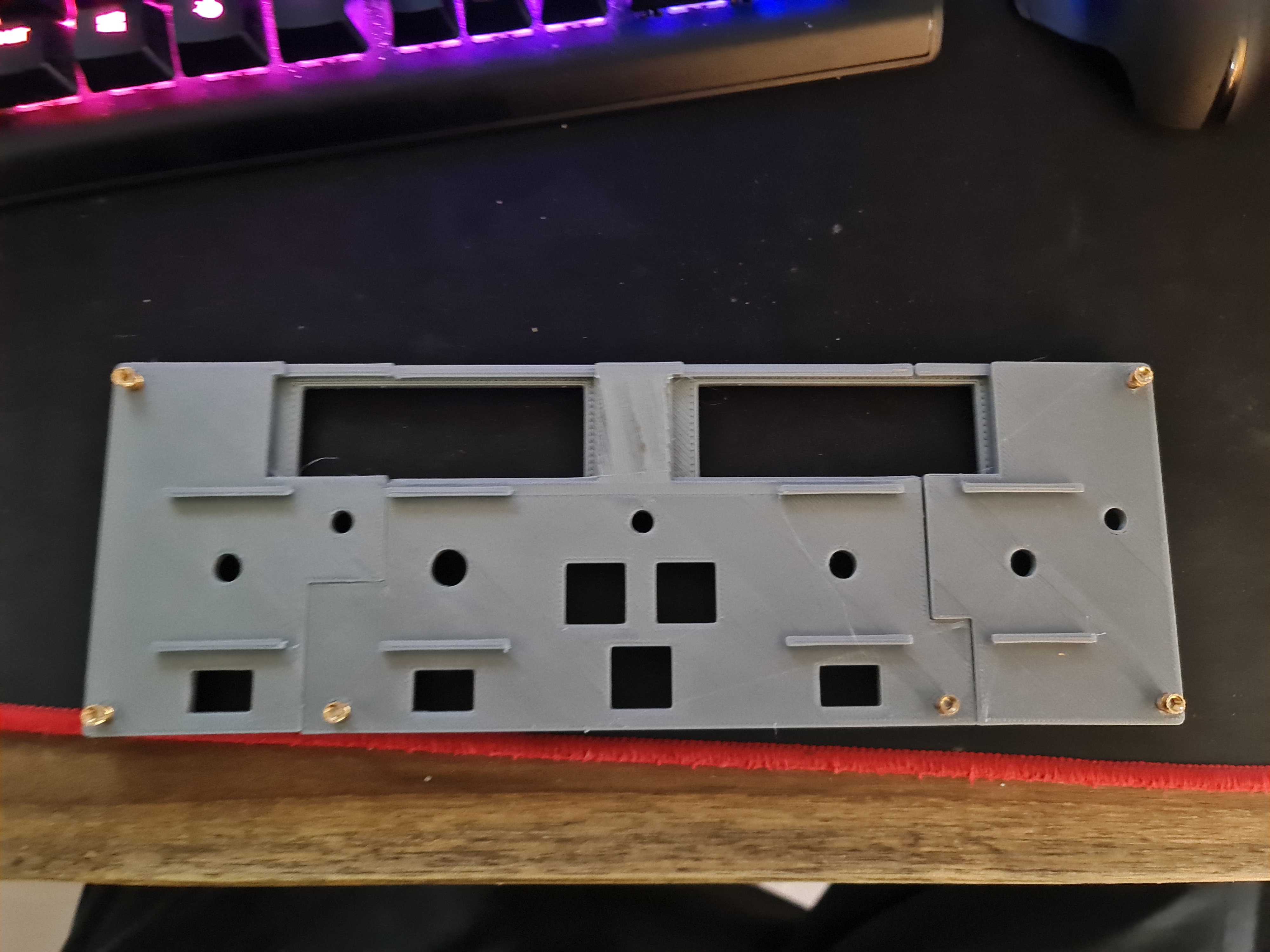
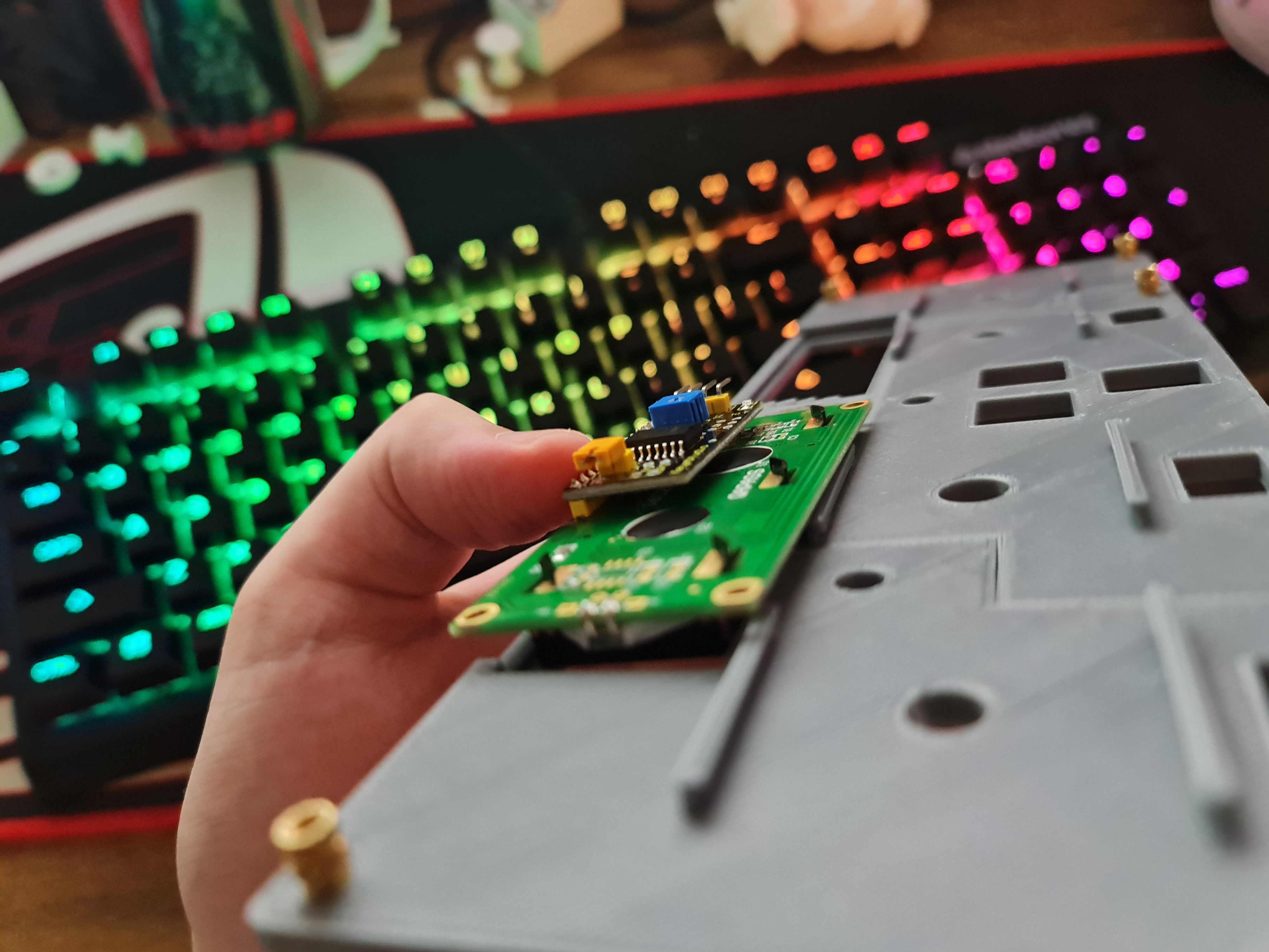
After the initial "awww..." moment, you can start to quickly see some faults. The first is that in this particular design, I'm using 2x 1602 LCD Screens. They have a large(ish) PCB around them. While I had factored in the top, part, I hadn't factored in the bottom part as I was drawing in the Rotary Encoder holds. This is probably where modelling the entire thing upfront would have saved some time...
There's also what appears to be a burn mark in between where the LCD screens will fit so I thought I'd better re-level the 3D printer and print again anyway. I don't have any pictures of it, but it largely looked the same and the LCD screens fit flush now. I'd then embark on a journey to build a smaller Korry switch - similar to that tested in the previous post. After several prints, it was clear that the smaller Korry would be too small to fit either a 5050 SMD LED or a 3mm LED bulb so I had to ditch the idea and build the external enclosure as part of the back plate. This process would waste a few days, but we eventually got there. This had to be printed with the button side up, so there was a lot of support material / waste to clear out too.
Now that we have an external enclosure for the Korry switches, it's time to test a few possible options.
Finalising the Korry Switch
Using the same dimensions as present in the new backplate, it was time to re-do the design. The main challenge and re-do here was getting the right size appropriate for the hole. When working within 1mm tolerances, you tend to fight both the printer and design. After 3-4 goes, we've got a good fit and button action (albeit the buttons themselves are kind of garbage).
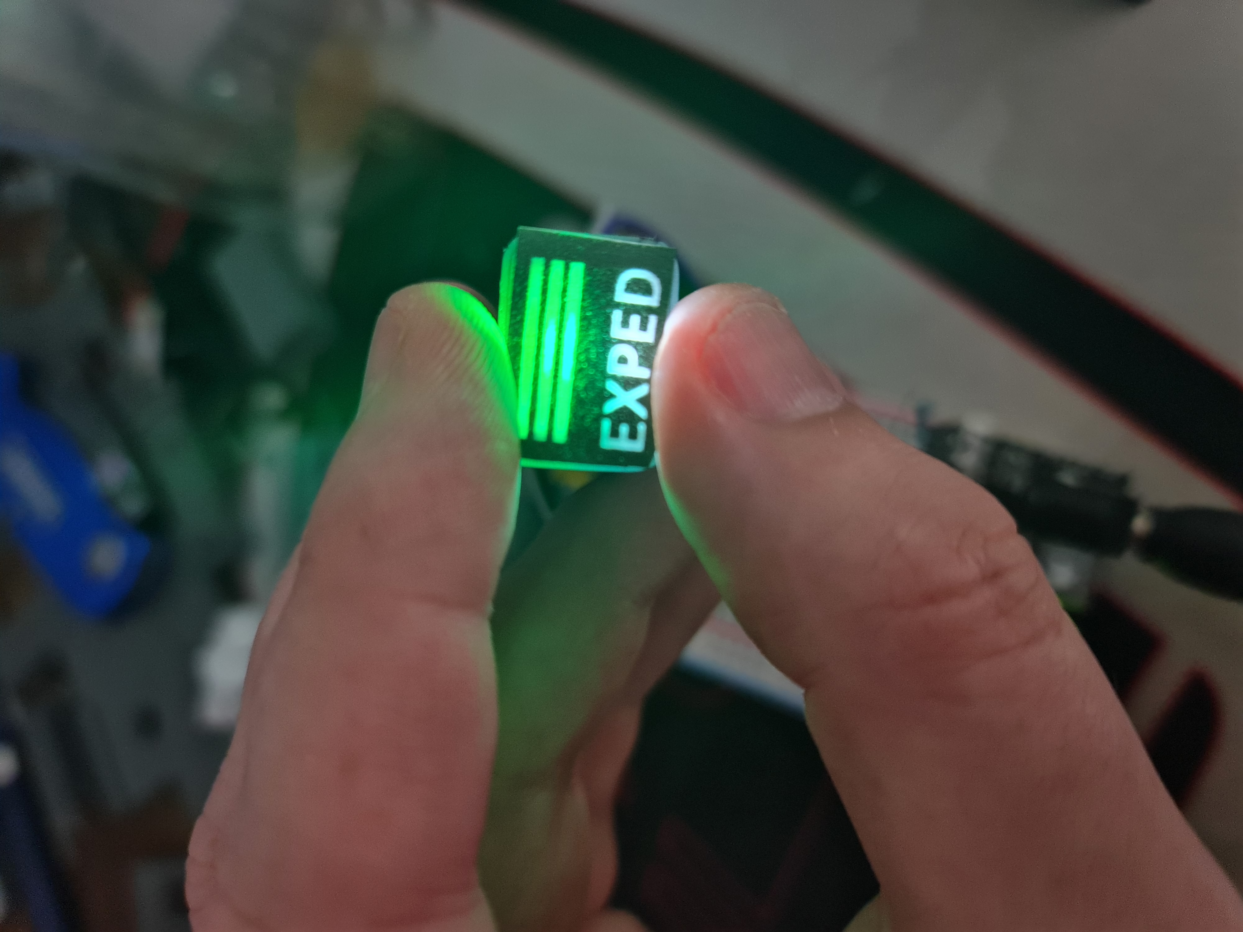
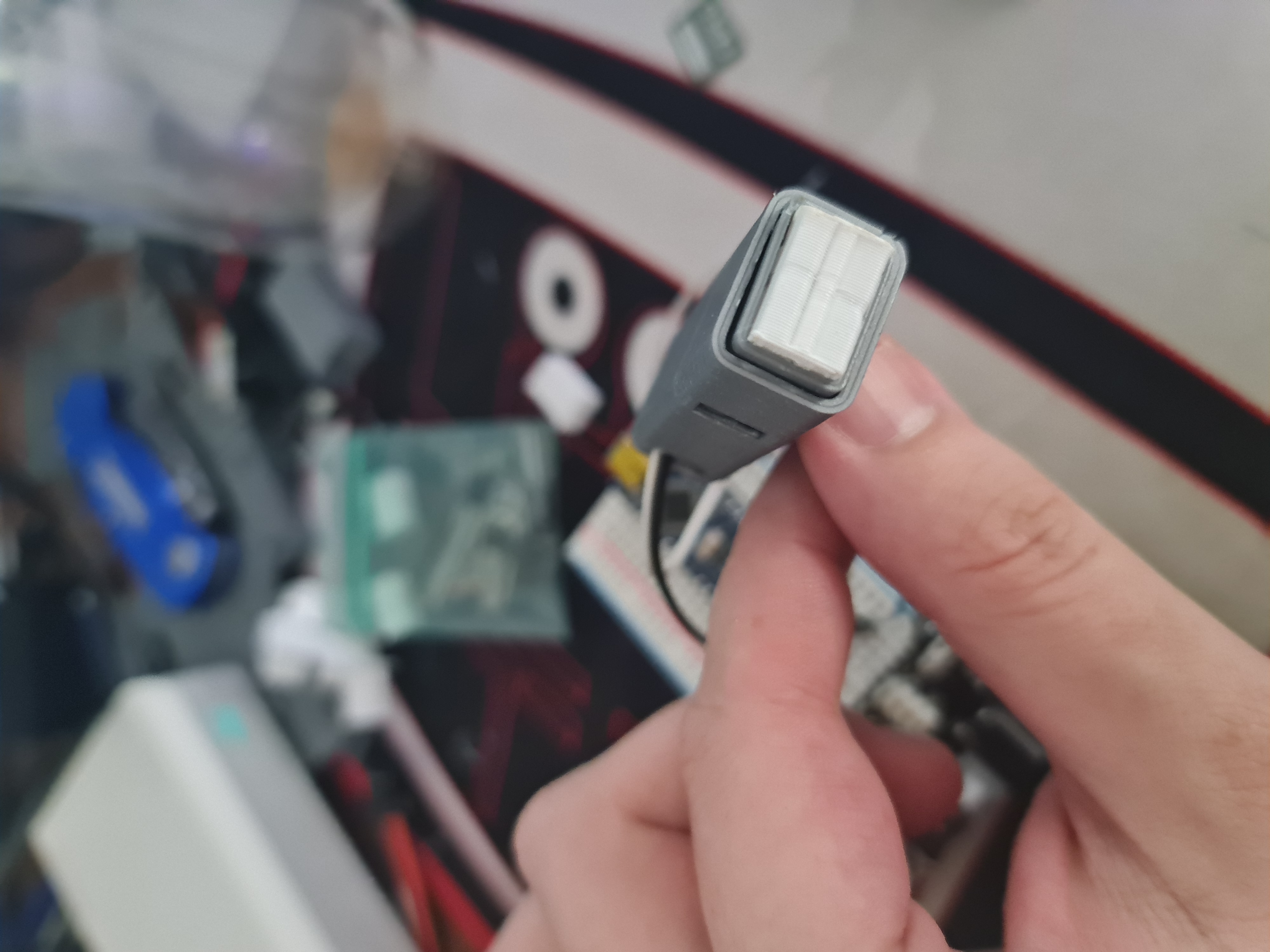
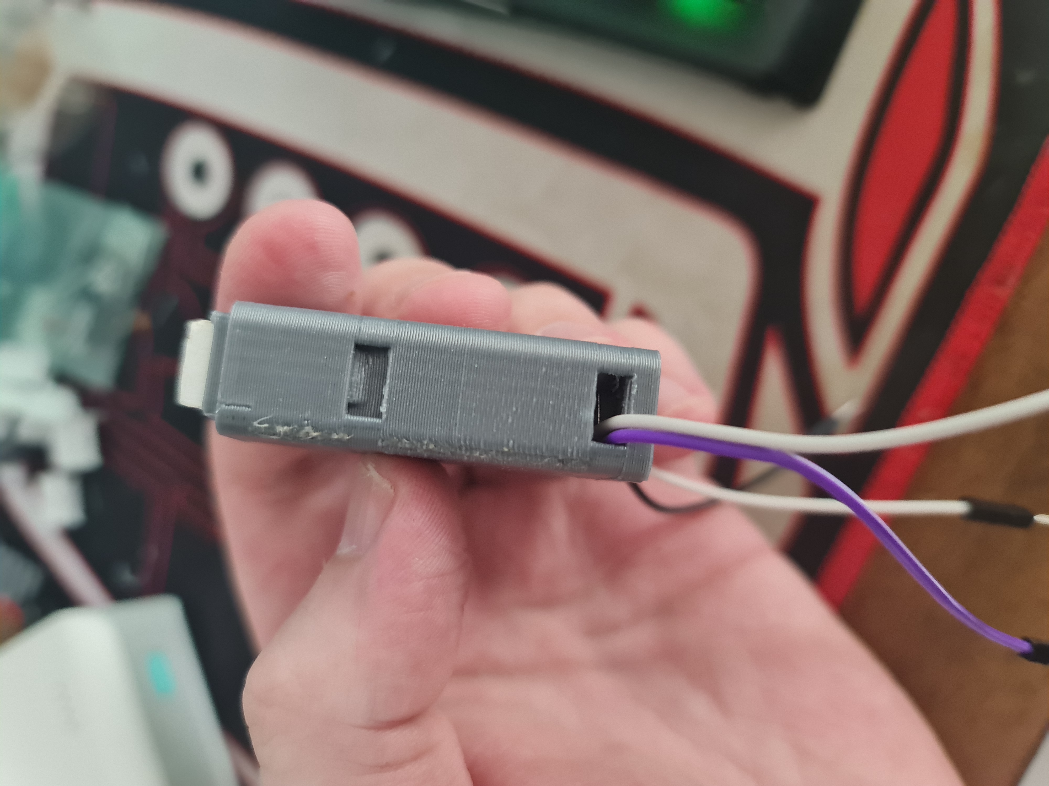
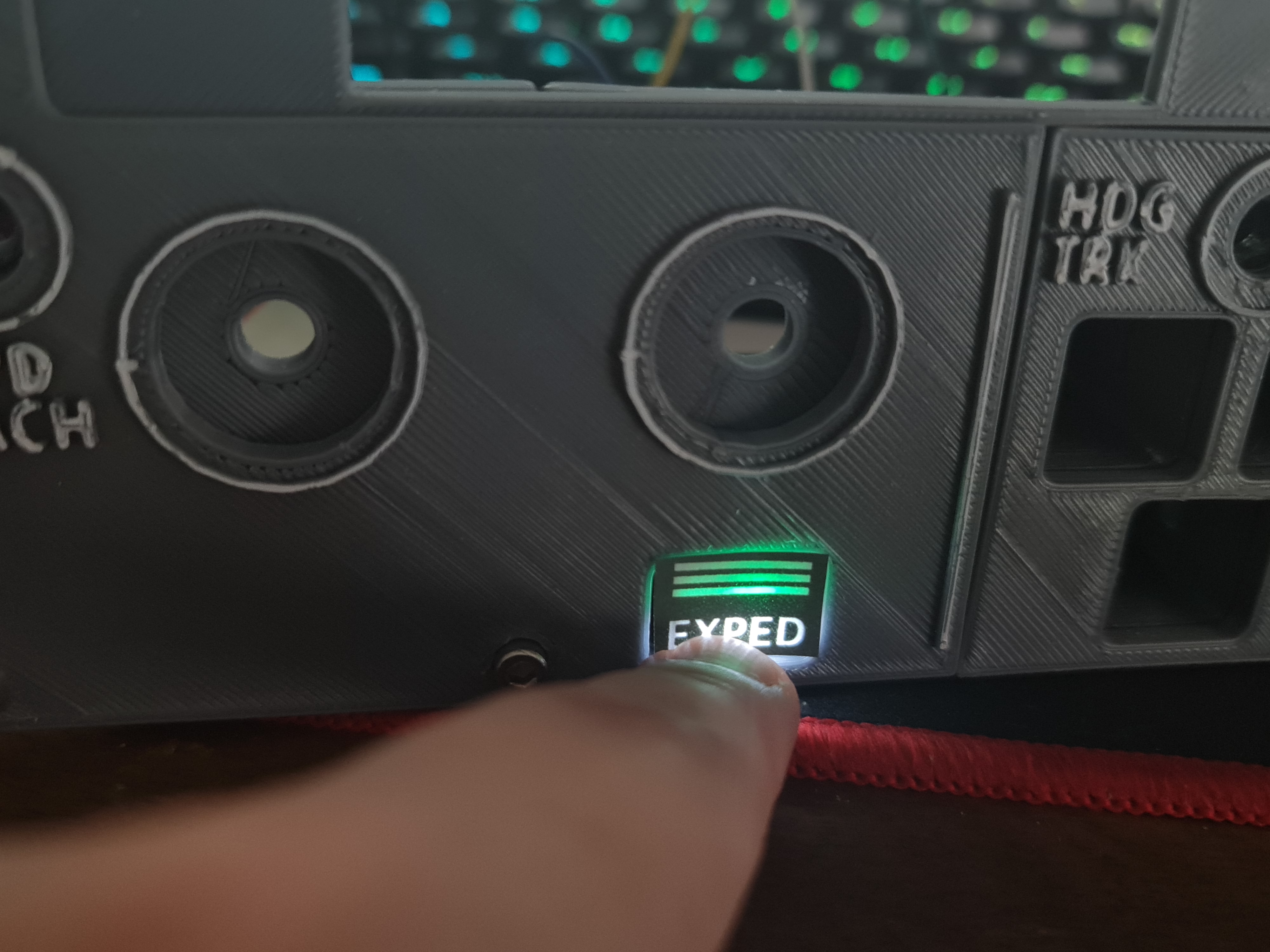
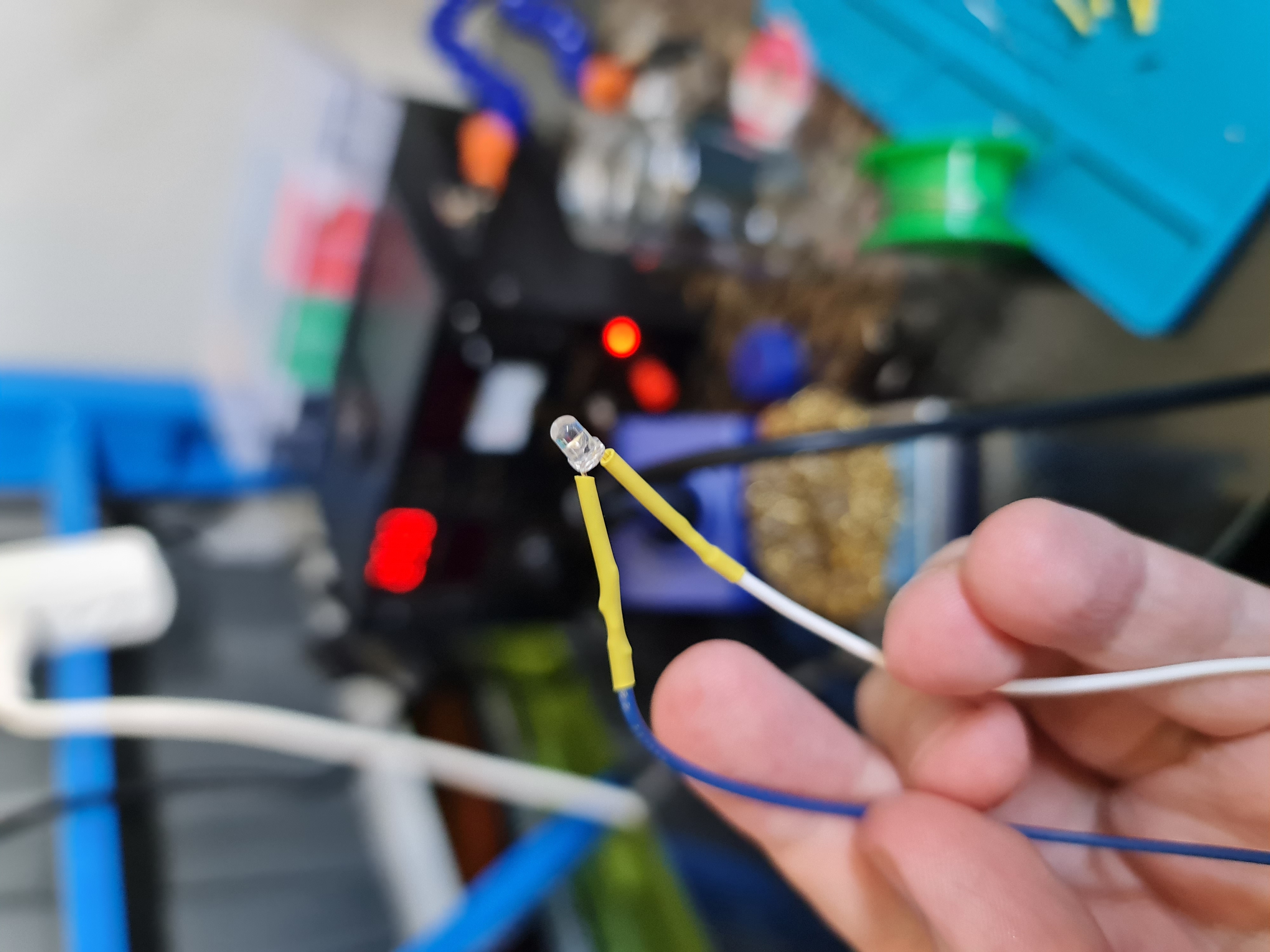
This... took quite a few goes (the diffuser, that is). Inside the chamber is a button and an insert. Green and White 3mm LEDs sit inside a small white diffuser thing, similar to the original Korry design. All that's left now is to solder up a bunch of LEDs, wires and buttons to fit inside of the FCU.
After getting the LEDs all installed and buttons all set up, it's time to put it in the main face plate and the result is pretty good. Still plenty of work to do and some transparent sheets to play with.